Part 3: Multi-Tile Shader Setup/Rendering in Maya.
Part 3: Multi-Tile Shader Setup/Rendering in Maya.
Brian Freisinger
October 18, 2011
Update: June 10, 2012 – To skip directly to how to set up for displacement jump ahead to part 4 of this tutorial series.
Also I’m no longer using the layered texture shader method and instead using the +/- Average node method as seen in Part 4. I’ll be updating this tutorial to reflect that in the future.
At the end of Part 2 you should have ended up with an object (Cube Primitive) laid out with multi-tile UV maps, and six texture maps you extracted from Mudbox.
There are now two ways you can assign your textures in a shader.
Again this applies to both texture and displacement mapping, but for this part of the tutorial we’ll just be looking at simple textures.
Let’s start by reloading the original cube scene you should have saved and then exported to Mudbox. If you forgot, just import your cube .OBJ you used in Part 2.
Simple Setup:
The first way is the down and dirty face by face assignment. I rarely use this unless I’m in a hurry or just want to run a couple tests without setting up a shader network.
It’s pretty simple to set up.
If we’ve got six tiles, and six textures, we simply create six shaders.
I’m using Vray here and creating VrayMTL shaders, but this will work the same with Lamberts, Blinns or anything else.
You’ll also notice I named them with a u#_v# so I can keep not only my surface assignments straight, I can also quickly identify which texture goes with which shader.
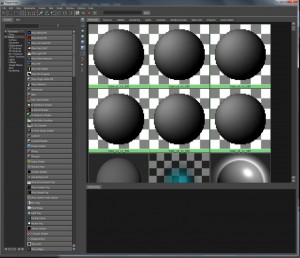
Now you simply grab each UV tile in order and assign the Shader to it.
This can be pretty tedious, but it’s simple and fast for diagnosing texture quality, or if you just want to check a couple of displacement maps on the fly without setting up a more complex network.
Once that’s done, it’s pretty straight forward texture assignment per shader.
There is one ‘gotcha’ when using .png files generated from Mudbox.
If you open the file in PhotoShop you’ll see it’s on ‘Layer 0’ with no background. Maya thinks that the empty background is a full alpha channel. So when it’s assigned to a shader, Maya tries to be helpful by adding a transparency or opacity channel.
So be aware, you either have to break the connection or lock the channel before adding the texture. I generally lock my opacity channels if I’m using this particular technique.
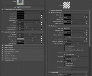
Both of these in Figure 23 have transparency added. The left is a generic Blinn, the right is a VrayMTL.
Double check this if you have render errors.
If you wanted to add spec maps, reflection maps, bump, normal, or displacement maps, it’s the same method, just the proper channels.
While this is the most simple and straight forward of setups, obviously it’s problematic for production because if you want to change Shader/Material attributes you have to make the same change to every shader, everytime. That’s why I only use this as a diagnostic tool, and not for standard production.
Master Shader:
The second and probably best method is to use a ‘layered texture’ node connected to a master shader: Blinn, Lambert, or Vray MTL etc.
The reason here is obvious, you have all your tiled textures under one node for surface property control. It takes a little more time to set up, but it’s worth it.
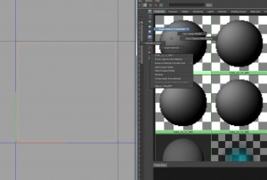
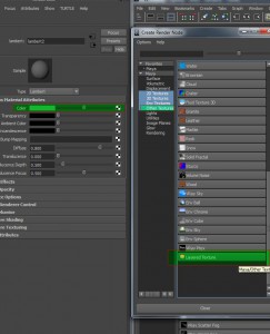
If you’re not familiar with the layered texture node it’s found under “other textures” in the HyperShade.
Using it can be a little tricky at times, but once it’s set up it can be invaluable.
Create a shader of your choice. For this one I’m going to use a lambert and name it “cubeMaster”
Create a render node under the “color” field, and assign the layered texture.
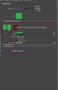
Once it’s assigned should see the layered texture attributes.
Now select to the right of of the green swatch in the layered texture attribute edtor and create another node.
Just to make things simple, create four more for a total of six layers.
Six tiles, six layers.
Once that’s done we’ll assign our first tile to the first layer.
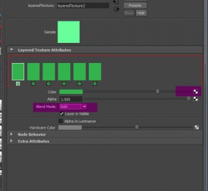
Take special node of the white boarder around what I have selected. It’s easy to mistakenly make changes to the wrong layer. Double check you see that white boarder that signifies “selected” before you make any changes or you might be doing it to the wrong layer.
You’ll also note in Figure 28, I highlighted the “Blend Mode”
It defaults with “none”, for a multi-tile texture set to work we need to set it to “add”
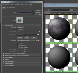
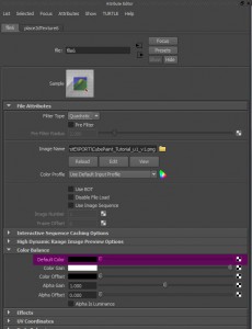
In the color field I’m assigning my first tile which is CubePaint_Tutorial_u1_v1.png
Because we’re using an “Add” Blend we’ll also need to set our default color to a solid black or it will contribute to the color.
If you forget to make this change it will start washing out your texture color until there is enough contribution to make it a solid white. It’s a very important step in the process to assure your painted textures and your rendered textures are 1:1
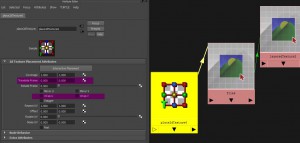
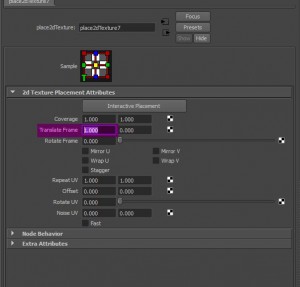
Next we’ll have to move down to the texture’s place2dTexture node and make some changes.
I have two areas highlighted in Figure 30.
The first is the translate frame. For our first tile we’ll do nothing, but this is important to take note of. It’s a bit counter intuitive to the process we’ve been using to count tiles, but the two fields of 0 and 0 basically mean u1_v1, or as it sees it zero translation in U or V. Basically it’s our first tile.
Second is the wrap u and wrap v fields. They’re on by default so your textures will continue repeating in each tile to infinity. Because we have textures for each tile painted we want to turn this off or the process will fail.
And that’s it, the first tile is done.
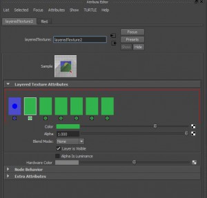
Going back to our layered texture node, we now see tile one is blue, signifying it’s got a connection. You’ll notice the white outline around layer 2 which indicates I have it selected and am now ready to make it an “add” blend and assign the texture.
I go through the same process, making sure my default color is black, but this time in the place2dTexture node I make one change.
As I pointed out in Figure 30, I left the translate frame fields at the default 0,0
For my second tile, which I saved as CubePaint_Tutorial_u2_v1.png, I need to change the field to translate 1 in UV x, and 0 in UV v
This basically equals our u2_v1 tag.
So the next layer would have a Translate Frame of 2 for your texture u3_v1 and so on.
When a lot of files are flying around it’s easy to make the mistake of punching in the wrong numbers for your textures, so double check that if your render looks wrong.
So now it’s just a matter of going through the whole process till you have a full assignment of your tiles to the shader network.
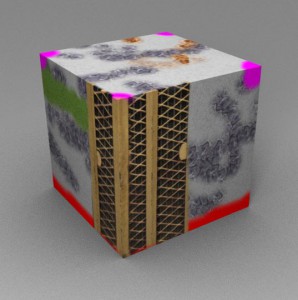
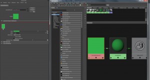
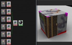
In the end your Hypershade should look like this, and as you can see I did a quick render to make sure it was working. I’m using a VrayMTL in this one, but as I stated it works in any of the standard Lambert, Blinn, Phong, etc shaders.
From this point on I usually copy the network and start connecting it to the other channels I’m planning on using; Spec, Reflection, Bump, Displacement, or in the event of using a SSS shader, I’ll plug it into the Sub-surface color, Scatter color, etc.
That’s pretty much it.
Part 4, Multitile displacement mapping
Update: June 10, 2012 – To skip directly to how to set up for displacement jump ahead to part 4 of this tutorial series.
Also I’m no longer using the layered texture shader method and instead using the +/- Average node method as seen in Part 4. I’ll be updating this tutorial to reflect that in the future.
Tags: CG, Vray, multiple UV, multiTile, multi-tile, UV mapping
Thank you for this tutorial!! It was great helpfull for me in exploring powers of Maya!:)
If you’re using VRay, you don’t need to set it up with the Layered Texture node like this. All you need to do is make sure your textures are named *_u1_v1.png, *_u1_v1.png, etc. For example, diffColor_u1_v1.png and diffColor_u2_v1.png. Those correspond to the UV layouts like you have above. But instead of using the Layered Texture, use 1 FileImport node and in there put in the name of the texture file in this syntax: diffColor.png. At render time, VRay will automatically load the correct u1_v1 map of UV at 0,0, then u2_v1 for UV 1,0, and so on.